Roundabouts, rotaries, or traffic circles, are unique segments of roadway in the Waze routing system. When a driver approaches a roundabout, a specific icon is displayed in the turn direction area of the display with a number corresponding to the exit count from the driver's entry into the roundabout or with a symbol of the movement through the roundabout. Manually creating a circular road will not produce these instructions.
What is a roundabout and what is not
Most parts of Europe use roundabouts regularly in intersections, while in the United States they are generally less common. In general when there is a clear roundabout in imagery, it is best to have it mapped as a roundabout in the road layer. There are a few cases that should not be mapped as roundabouts.
| Description | Image |
|---|---|
| Streets intersect, but there is no center island preventing left turns. There are no signs indicating a roundabout approaching the intersection or painted on the ground. | 
|
| A single road segment leading to a cul-de-sac should be drawn as a dead end. With very large roads it might be advisable to create a three-segment loop but not a roundabout. | 
|
Creation from an intersection
Oftentimes, when streets become more congested, planners will install a roundabout to get traffic to flow more freely. This section shows the steps to get from an existing intersection to a new roundabout.
The situation starts out like this, where the roads are no longer aligned with the new plan, and now there is a roundabout which we need to get created in Waze:
This situation is fairly simple because all the segments are connected together already.

The first thing to do is move the junction to the center of the roundabout. This is as simple as it sounds: click and drag the junction to where it should be.

Which gives us this:

The two southern segments need to be disconnected from the center node and joined together below where the new road arches along the bottom of the screenshot. Once those are in place, draw the missing segment in between the roundabout location and the roads to the south of the roundabout.
If you look closely, you will see this roundabout actually does have four entry/exits, so let's also draw in the western road as just a small stub, for future use. This will also cause the roundabout to give the driver better instructions in terms of which exit to take, as a driver will see the stub exit in real life, and so will count that as an exit.
Once those are all created, go ahead and save the work.
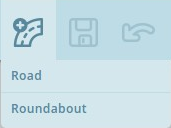
Hover the cursor over the road with plus sign icon the right side of the toolbar and click Roundabout. You can also use the keyboard shortcut which is the letter o, selected because the shape of the letter is round, like a roundabout.

Move the cursor to the center of the actual roundabout. The cursor will be a crosshair + to indicate it is in roundabout creation mode. Click once at the center and then move the mouse any direction towards the perimeter of the roundabout. An orangish circle will grow and shrink as you move the mouse, and the numbers in the center of the circle display the diameter the roundabout will be.

Click once when satisfied with the size and shape of the roundabout. What happens now is that the map editor creates new 1-way segments in between each road segment the circumference of the roundabout comes into contact with. Each of those segments is cut off and connected to the roundabout with allowed turns already set. All of these segments are shown in orange because they are not saved yet.
Any segments completely within the roundabout area will be deleted.

Just as with drawing new roads, the segments of the roundabout which were created in the last step must be confirmed in order for them to appear on the map in the Waze app. That is, each segment needs the country, state (where applicable), and city. Please see the Updating details to confirm the road section for details on this process. In Waze, we do NOT name roundabout segments. These segments remain unnamed using the "No Name" checkbox for street name to enable proper routing. If the roundabout is a named circle on local signs, then add a Place area type set as a Junction / Interchange filling the center area or covering the roundabout as appropriate using the name that appears on the local signs.
When the process is complete and the Save button has been clicked on one last time, this is how the new roundabout looks:
For further reference, please watch this video on roundabout creation.
Oval and very large shapes
If an oval or elliptical roundabout is required, hold down the Shift key. At this time only oval roundabouts along the North/South or East/West axis can be created. If an alternate shape or axis is desired, create a circular roundabout that is close to the correct shape and adjust the geometry nodes manually.
Note that roundabouts cannot be created over a maximum of 100 m (328 feet) in diameter because of the danger of erasing all roads in the center could accidentally wipe out an entire city of roads. If a larger diameter is required, use the same steps described above to alter the shape by adjusting the nodes as required.
Improving manually drawn roundabouts

A well-meaning editor probably just didn't know how to create a new roundabout, so it was created by hand manually setting the segments as close to rounded as possible. The real problem is that Waze will not navigate these segments like a roundabout. This section of roadway will produce "turn right and then turn right" if being driven straight through. This is not what the driver will expect:
A proper roundabout, when being driven straight through, will tell drivers "at the roundabout, continue straight", "at the roundabout take the second exit" or some other numbered exit instruction depending on the size and number of nodes in the roundabout.

The first step is to select and delete all the segments that make up the circle connecting the roads leading into the roundabout. That can be done individually or as a group.

Next, extend the segments deeper into the center of the roundabout area. They need to end inside the final diameter of the roundabout, otherwise they will not be linked automatically during the final step of creating the roundabout. During this step be sure to center the roadway segments from the middle of their respective roads. Unless the actual road has a significant divider between the incoming and outgoing lanes on a road, avoid creating two separate one-way roads leading into and out of the roundabout (See Below). Press Save to ensure there are no errors before going to the next step.

Now select Roundabout from the pencil icon, or hit O on the keyboard. The cursor turns into a small cross. Click and hold the left mouse button at the center of the roundabout area and extend outward until you reach the proper diameter. When the diameter is correct, release the mouse button to create the new roundabout.
If the aerial imagery does not show a new roundabout that exists today, use the GPS tracking layer to estimate where the center of the roundabout is located.

After saving the roundabout will be red. This indicates that the roundabout road segments have not been confirmed. To do that select the roundabout segments and ensure the country and state are selected. Also set the city or mark it as no city. Roundabout segments usually have no name, so check the None box next to the street field. Named roundabout segments do not cause problems with routing or navigation instructions, however, and may be necessary for house numbers if houses lie directly on the named roundabout. An area place can also be drawn for the named roundabout under the category Junction / Interchange.
After confirming the individual roundabout road segments, there is now a properly-formed roundabout which will give the correct routing instructions:
Note that roundabouts should never be created with just one segment. Roundabouts should be intersected by two or more road segments. Review the Junction Style Guide for information on creating a loop or a dead end.
Creating a roundabout from nothing
Draw all of the road segments that will lead to the roundabout and ensure they extend into the center of the roundabout area. Use the visual map to align the roads. From there, create the roundabout just as is described in the two sections above.
Note that there must be at least one road segment partially inside the area of the roundabout being created, otherwise no roundabout will be created.
Adjusting geometry
When a segment of a roundabout is selected, the geometry points (white circles) will appear. Each of these circles can be moved by dragging them with the mouse to align better with the visual map or the GPS traces.
When initially creating a roundabout, it is possible to create an oval or elliptical shape by holding the Shift key when stretching the diameter before it is created. Only oval roundabouts along the North/South or East/West axis can be created. If an alternate shape is desired, adjust the geometry points as described above.
Road type
It is possible to have multiple types of roads ( Street , Primary Street , Minor Highway , etc.) meeting at a roundabout.
To minimize inefficient routing, it is important to be careful with the road type assigned to the Roundabout itself. Any routing penalty going from connected roads to the roundabout must be kept to a minimum, but it should not be too "attractive" where routing through it is encouraged when unnecessary.
The road types of interest in are, in order from highest to lowest, Freeway , Major Highway , Minor Highway , Primary Street , Street , Parking Lot Road , and Private Road . Since a Roundabout is not a Limited Access Interchange, two Freeways should never meet at a roundabout; however, it is conceivable that a Freeway might begin or end at one.
To determine what road type to use for the Roundabout:
- Identify the two connected segments with the highest type listed above:
- If a particular road goes through a roundabout, count the road as two separate segments, one on each side of the roundabout.
- If a road on one side of the roundabout is a divided roadway made of two one-way road segments, count the pair of one-way segments as a single segment.
- The two connected segments with the highest type may have the same type or different types.
- If a ramp connects to the Roundabout, use the road type to which that ramp connects.
- Select the roundabout and set the road type as follows.
- If the two highest-type segments have the same type, use that type.
- If the two highest-type segments have different types, use the lower type of those two segments.
Waze supports two different styles of roundabout navigation instructions. One style instructs simply to turn or continue at the roundabout, while the other instructs how many exits one must pass before leaving the roundabout. The US editing community terms these two instruction styles as "normal" and "non-normal" respectively. The term "normal" is used here in its mathematical sense to mean "orthogonal", "perpendicular", or "at right angles".
This section will explain the difference between a normal and a non-normal roundabout.
Normal roundabouts:
- Require all of the following
- 2-4 nodes.
- All exit nodes aligned within "normal" range of the entry node
- A radius less than 25 meters
- Provide the following instructions:
Non-normal roundabouts:
- Require at least one of the following:
- 5 or more nodes.
- Nodes outside the normal roundabout angle range
- A radius greater than 25 meters.
- Provide the following instructions:
A roundabout can be both normal and non-normal at the same time depending on your entry node, because the roundabout angle is calculated from where one enters the roundabout.
Roundabout angle
The roundabout angle is the angle of any segment connected to the roundabout from the perspective of the origin. This is basically the same as the central angle of a circle. The actual turn angle of the segments is irrelevant.
To explain;
- Draw an imaginary line through the center of the roundabout to the other side of the roundabout from junction node where the origin joins the roundabout. This will represent a 0° roundabout angle, any deviation to the right or left will increase the angle.
- Draw another imaginary line across the roundabout through the center and perpendicular to the first imaginary line. This will represent a 90° roundabout angle to either side.
| Roundabouts | |
|---|---|
| Normal | Non-normal |
 |
|
| All other segments are within the allowed ±15° from either 0° or 90°. | Not all other segments are within the allowed ±15° from either 0° or 90°. |
Examples
Segment angles
- Since the angles of the segments approaching the nodes do not matter, both of these layouts will give the same instructions. Only the angles between the nodes and the center of the roundabout (roundabout angles) determine which instructions are given.
Three incoming segments
- Let's assume this roundabout has a diameter of less than 25 meters, so the other criteria are met for normal instructions.
- Coming from node #1, this is how we see the roundabout:

- Both exits 2 and 3 have roundabout angles within the normal range (90°±15° & 0°±15°).
- These exits will get an instruction to "turn right" or "continue straight".
- Coming from node #3, this is how we see the roundabout:

- Exit 1 is within the normal roundabout angle range, but exit 2 is not within the normal roundabout angle range.
- Even though one of these exits is within normal range, the roundabout itself is ‘non-normal’ and both exits will get the "take the X exit" prompt. The entire roundabout must be normal to generate "turn left", "turn right" or "continue straight" instructions.
- Exit 1 is within the normal roundabout angle range, but exit 2 is not within the normal roundabout angle range.
Entries and exits
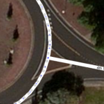
The road segments leading into and out of a roundabout are generally drawn as simple two-way roads connected perpendicular (90 degrees) to the roundabout circle itself. This makes it easier on the user to visualize the map into reality by not having the incoming lanes appear separately on the map and only see the exits.
In some large or irregular roundabouts the incoming and exit roadways may be so far away from each other that it would be better to have them split into two separate one-way segments. Each entry or exit segment should be connected to its own node on the roundabout. This will almost always cause the roundabout instructions to be non-normal. Due to historical reasons, some regions of the USA have a preponderance of normal or non-normal roundabouts, and the users in those reasons are accustomed to one or the other set of instructions. Check with your regional leadership to determine which instructions are preferred when drawing roundabouts.
Multiple segments at one node
In general, it's only appropriate to connect multiple segments to a single node of a roundabout if the exit leaves the roundabout to the left of the entry, such as, for example, both directions of a divided highway meeting at one node. This will be treated exactly like a single two-way segment in navigation instructions.
Do not connect an entry belonging to one road to or past an exit belonging to the next road to the right, as this causes the first exit not to be counted and the subsequent exits to be numbered incorrectly. Even if the movement into and out of the roundabout is prohibited at this point (often the case in roundabouts with at-grade connectors), if it is physically possible, users will tend to count it as the first exit, and we need to provide a consistent experience when mapping.
Do not connect more than one exit (either two-way segments or outgoing one-way segments) to the same node at a roundabout, as this causes Waze not to number any exit. In these cases Waze will show an empty circle for the roundabout instruction and will simply truncate the spoken instruction to "at the roundabout."
Moving junctions and disconnecting roads
When adjusting roundabouts, drag the junction nodes and move/delete the geometry points of the segments. Do not disconnect or reconnect roads just to adjust angles. Apart from the loss of turn data that happens with disconnections, some nodes can't be deleted from roundabouts, and changing segment IDs within them (caused by cutting and merging) can cause them not to work properly.
At-grade connector
Some roundabouts are designed with physically separated bypass roads or at-grade connectors (AGCs). In many cases, roundabout at-grade connectors can be mapped just like any other, but some roundabouts with AGCs have persistent routing problems.
Correcting inappropriate avoidance of roundabout AGCs
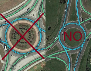
Where AGCs have been built to allow right-turning traffic to avoid the roundabout altogether, Waze might send traffic through the roundabout anyway, if Waze thinks the roundabout is even a few seconds faster at a certain time of day. If there are any difficulties with assigning traffic to the correct segments at this junction, Waze may be incorrect. This is often confusing to drivers when it is contrary to guidance or regulatory signs.
Junction boxes cannot be applied to control turns in roundabouts, so other approaches have been explored.
What not to do
Do not junction the incoming and outgoing segment at the same node in order to prevent the redundant turn. Multiple segments at one node causes incorrect exit numbering, and, in some cases the distortion can cause incorrect normal instructions, (for example - "at the roundabout, turn right" to users continuing straight, if they travel through only 90° of the roundabout from entry to exit).
Do not move the incoming segment after the outgoing segment to make Waze avoid the exit. This is also a distortion if the roundabout and can cause incorrect roundabout instructions,
| Because the following solutions are hacks, do not use them unless improper avoidance of the at-grade connector has been persistently demonstrated in real route testing; work under the supervision of local leadership. |
Fake U-turn prevention
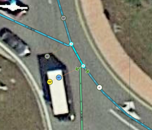
One solution is to activate the three-segment U-turn penalty. This treats the entry and the next exit as opposite directions of a divided road, and the roundabout segment interstitial segment as the median of the divided road, over which U-turns are not permitted. To use:
- Move the nodes so that the roundabout segment is 45.93 ft (14 m) long or less.
- On the entry and exit segments, move geometry points very close to the nodes so that at the roundabout segment, the entry and exit segment are within five degrees of parallel.
- Note that the algorithm actually measures parallelism and not simply the sum of angles, so it ignores any geometry points on the interstitial segment when checking for parallelism.
If all three criteria are satisfied (three segments in the movement, roundabout segment length and parallelism), a large penalty will be applied to the movement into and out of the U-turn, causing the at-grade connector strongly to be preferred in routing.
This solution is only compatible with non-normal roundabout instructions, as there will be too many nodes to meet the criteria for normal instructions. It's also difficult to use where the entrance of the first road is very far away from the exit of the next road.
Fake or real detour prevention
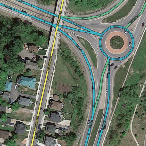
Another solution is to activate the big detour penalty. This treats the movement into and out at the next exit as a detour away from the AGC. To use:
- Make sure that the segment before the AGC, the AGC and the segment after the AGC all share a name.
- If no real named or numbered road continues through the AGC, a fake alt name can be used, such as "BDP" or "roundabout hack."
- A turn instruction override will probably be necessary to force a turn instruction into the AGC.
- Make sure that these three segments all share the same road type group.
- Along the path to be avoided, select the entrance segment that leads from the roundabout to the end of the AGC (the last segment of the detour), remove all names (they will be inherited in instructions from other entrances) and change the road type to be of a different group from the AGC and its bracketing segments.
- To ensure proper pruning behavior, the routing road type of this segment may be adjusted to match those it connects.
If all detour criteria are met, a significant penalty will be applied to the movement away from the at-grade connector, through the roundabout and back, causing the at-grade connector to be preferred in routing.
This solution is compatible with both normal and non-normal roundabout instructions but can be difficult to use if the roads connected by the AGC are of different road types or are not highways. It is particularly indicated when a numbered highway is actually carried by the AGC, and the movement into the roundabout is a true detour.


