| This revision of a section is currently undergoing modifications. The information presented should be considered a draft, not yet ready for use. Content is being prepared by one or more users. Do not make any changes before you send a private message to this user. Please use the talk page for thoughts and ideas on setting up this content. |
Three-way
Right angles

|

|
The simplest junctions often resemble a "T" and are considered diverging or branch roads. The branch road will normally meet the main road at nearly a 90 degree angle. This is the simplest situation to map, as the physical and logical views of the roads match up well.
Odd angles

|

|
Some roads meet at odd angles. The initial urge will be to represent the junction as it is in the physical world - two lines running into each other at a sharp angle. But there are issues with this method.
- Depending on the angle, the client may give a "Keep Right" instruction to the driver when a "Turn Right" instruction is more appropriate. If Minor Highways or above are involved, you will actually get an "Exit Right" which can be confusing in many situations.
- In some cases, no instruction will be given at all. In the worst case, the routing server may determine that it isn't possible to make a very sharp turn angle and not suggest the turn at all (in the example image, heading south, then turning left, to head east).
- Automatic map errors may appear with turns from one direction as the path of the turning traffic is "too far" away from the actual junction (in this example, traveling south, then turning left to head east).

|
To eliminate ambiguity, map the junction from a logical point of view. Since basic "Turn Left" and "Turn Right" instructions are desired, tweak the intersecting angle so it resembles a basic 90 degree intersection. Add geometry nodes to make the branch road leave the main road at close to 90 degrees, then gradually curve the road to match the true departure angle. This will produce a junction that logically works like a basic 90 degree junction, but it also fits the reality of the physical world.

|
Here is a completed real world example which provides the expected turn instructions and "catches" turns from all directions avoiding automatic problems for missing road when they are "too far apart."
Name changes on straight path
For conditions where the straight through route changes road names, it is important to identify which segment is drawn as the straight route and which is shown as the right turn from the main road. As the How Waze Determines turn/keep/exit maneuvers page explains, segment names and geometry are very important in determining what navigation instructions are given.

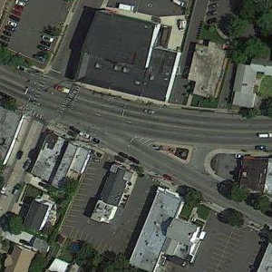
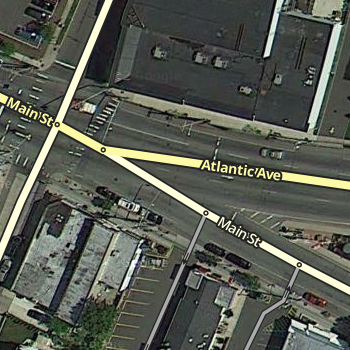
In this example to the right, the multi-lane surface street is known as Main Street to the west and Atlantic Ave. to the east. The name change occurs when Main St. branches off as a regular surface street. That is the human description, but a more technical description would be that Main St. travels in a perfectly straight line and Atlantic Ave. branches off of it. But if we map it that way in the editor, we create a major problem.

Since the multi-lane segment of Main St. and the regular street segment of Main St. have the same name, the routing engine automatically considers that to be "straight". If the two sections line up in a straight line the way they appear from the sky, then we are reinforcing the idea that "straight" is Main St. to Main St. But as a typical driver would want, "straight" should be the path that remains on the multi-lane roadway, regardless of what name it uses.

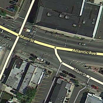
To make sure the routing engine understands the proper treatment of the junction, we have to be deliberate with the segment geometry of all three involved segments. We end up with something like the image on the right. Now the geometric definition of straight is the multi-lane portion of Main St. onto Atlantic Ave., since we have made that transition as close to zero degrees as possible. The regular street portion of Main St. now branches off at an angle close to 90 degrees. The routing engine should recognize that a turn is required. So the result is that Main St. to Atlantic Ave. has no announced turn, and multi-lane Main St. to surface road Main St. has a turn announced. Exactly what most drivers would expect in the real world.
Steep angles with exits and keep right or left

|

|
A ramp from a highway is another good example where additional geometry nodes are helpful. Especially since most ramps diverge at a very small angle from the road. The drawback in this case is it may be hard to see and click on the turn restriction arrows in the editor.

|

|
Therefore add one more geometry node to make the departure angle at the junction closer to 10 or 20 degrees. (dogleg) See the discussion on controlling turn instructions for details on those angles. Now the arrows are visible and accessible. Note that also pressing s in the editor will spread or separate the arrows at a junction, if a arrow is still difficult to reach. See the keyboard shortcuts article for more tips on other keys.
With this adjusted angle, this junction now behaves as expected and the turn restrictions can be easily accessed.
Four-way
Right angles

|

|
The second simplest junction category is a "+" or "cross" four-way junction that intersects at 90 degrees. These roads are simple to map as the logical and physical views of the roads match up well. These instructions follow the similar guidelines and solve the same problems as diverging roads.
Odd angles

|

|
Similar to diverging roads that intersect at odd angles, crossing roads can do the same thing. When these intersections are mapped as seen here with these odd angles, complications can occur.

|
Geometry nodes bring the actual junction close to 90 degrees. Zoom in to the intersection and add a single geometry node on each side as close to the junction point as possible. This will give the more desirable 90 degree angle, and it will still be virtually invisible to client app users making it look like the physical world. This image is what is seen when zoomed in as close as possible. Zoomed back out, it looks just like the map image showing the junction without any geometry nodes.

|
Here is a real world example at a close zoom level where you can still see the geometry adjustment. With that adjustment in place, the junction will produce predictable turn left and right navigation instructions while the roads still appear to meet at the real-world angle in the client app.
Divided road intersections
Many of the principles stated above apply to intersections between divided roads. Usually, divided road intersections should look like the traffic lanes they represent. "Box" shaped intersections are easiest to draw, maintain, and to explain to other editors. Only use variations when they are needed.
Read through the pros and cons of the intersection types below and select the best suited.
| Insert examples of a divided road intersecting a two-way road, two divided roads intersecting each other, 3-way intersections involving divided roads, intersections where one road changes between divided/2-way at the intersection... |
Box and partial box intersections
This type of intersection is most useful in intersections where the traffic queues in a median segment that is long enough to justify being mapped, especially if the one-way roads would have to deviate greatly from their physical location to meet in a single point for a bow tie. This also allows the map to route correctly while representing the actual geometry of the roads in real life, which is more intuitive to users.
Do not use this type of junction if the crossbar will be less than 19.69 ft (6 m). Waze has difficulty in capturing average speeds for short segments, especially in wide intersections where traffic travels a fairly curved path rather than sticking close to the segment. Add in the inaccuracy of many phone GPS units, and you may have a situation where the reported positions of some of the vehicles are never on the segment during the maneuver.
When creating three way and four way intersections, if the cross street changes names at the junction, make sure that the segment(s) have no name. This will cause the segment to inherit the appropriate name depending on the direction of travel. This center segment will not be included when you choose "Select entire street".
Three way divided road intersections are easier to edit accurately than four way intersections.
| Insert examples: divided road ends at 2-way road (single point if both lefts are allowed and u turns are not); divided road ends at divided road ("triangle" in median if both lefts are allowed and u turns are not); 2-way road ends at divided road (easy). |
If possible, lay out the intersection to resemble reality. When all divided-road U turns are allowed at an intersection, or when disallowed U turns are effectively restricted in Waze by existing restricted left turns already, use the guidance in this section.
When a U turn must be restricted, but both of the left turns that make up that U turn are allowed on their own, follow the guidance in Avoiding U turns below.
| Insert examples: divided road intersects a 2-way road (≠); two divided roads intersect (#); intersection where one road changes between divided/2-way at the intersection... |
Bow tie

The "bow tie" intersection method makes it easy to take separate control of left turns and u-turns at divided-road intersections. It also allows Waze to correctly draw conclusions about where traffic queuing occurs.
Use it only
- at 4-way divided road intersections (between two divided roads, or between a divided road and a two-way road).
- only when necessary to prevent u-turns while allowing left-hand turns.
- The angles at the single bow tie intersection can reasonably be made 45 degrees or less. Otherwise, drivers going straight through will get an instruction to turn or stay right in right-hand traffic countries (turn or stay left in left-hand traffic countries)
- Because of the awkward appearance of the bowtie, consider using other methods, such as the U-turn prevention mechanism immediately below. It is common for drivers to report map errors due to the appearance.
Avoiding U turns in box and partial box intersections
| For the latest discussion on this section please visit the wiki forum thread. |
| It is possible for this method to fail to prevent U-turns in certain circumstances which are presumed to be unusual. If you observe this method to fail when it is implemented properly, please report it in this forum thread |

U-turns can be avoided where two divided roads intersect (in a # configuration, aka a Box junction) or a divided road intersects an undivided - a single two way segment - road (in an H configuration junction)
- The U-turn we want to forbid is one incoming one-way segment, one median segment, and one outgoing one-way segment.
- there is a median segment of length less than 52.49 ft (16 m).
- The portion of those two segments closest to the median segment must be within ±5° of exactly parallel.
A convenient way to check for parallel is relative to a reference segment that connects the A and B nodes of the median segment with no geometry nodes. A median segment with no geometry nodes is its own reference segment. The reference segment can be deleted after the check is complete, if appropriate. Check two angles: X -- the angle between the incoming one-way segment and the reference segment Y -- the angle between the outgoing one-way segment and the reference segment. If the sum of these two angles is within 5 degrees of 180, then rule 3 is satisfied.
In the example below, angle X is 102 degrees and angle Y is 75 degrees. The sum is 177, which is within 3 degrees of 180. Therefore rule 3 is satisfied.

The Waze routing algorithm assesses a penalty for a double-left turn in right-hand traffic countries and a double-right in left-hand traffic countries.


