(→Road Level: Explained more how it is used in WME and Client App) |
(→Removing junctions with only two segments: update to include prefered deletion method.) |
||
| Line 152: | Line 152: | ||
|} | |} | ||
Once you are certain there is no reason to have the extra junction, there are | Once you are certain there is no reason to have the extra junction, there are three methods to remove it. One method highlights the junction and deletes it, one highlights the two segments and bridges them together, and the last method will drag one junction on top of the other junction. | ||
=====Delete key or trash can icon===== | |||
This method is the preferred method, because it enables the WME to alert you when there are legitimate differences between the segments. With the mouse select the junction point between the two segments. Look for the trash can icon at the upper right corner of the WME screen. If it appears press it to remove the junction. It will place a geometry node at that point automatically. If you need to remove the node, you can do so by highlighting the segment and hovering the mouse over the point of the prior junction. It will display the node and you can press the '''d''' key to remove that node if necessary. | |||
If the trash can icon does not appear, something about those two segments are different possibly including the city name, street name, or direction of travel. | |||
=====Bridge segments===== | =====Bridge segments===== | ||
This method is | This method is less desirable because when used it causes the road level of the segment to increase by one. | ||
[[Image:MergeJunc-2a.png|left|350px]]With the mouse, select one of the segments. Then, while holding down the multi-select key ('''Control''' for Windows/Linux and '''Command''' for Mac) select the second segment. If the two segments have the same properties including direction, a small bridge icon will appear above the junction. Click the bridge to merge the two segments, eliminating the junction between them. A geometry node will be placed where the junction was previously located. To remove the node (if necessary), select the segment and hover the mouse near the old junction. The geometry node should be displayed. Then, press the '''d''' key to remove the unwanted node. | |||
When the segments are '''different''', the bridge icon will '''not''' appear at the junction.<br clear="all" /> | |||
=====Drag together===== | =====Drag together===== | ||
Revision as of 00:06, 24 February 2013
Back to Editing Manual
This article covers creating and editing road segments. Be sure to read this whole article to ensure you fully understand all aspects of how segments operate in Waze before you start to create and edit roads on the map.
Creating a new road
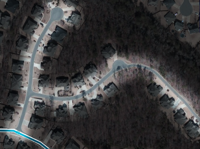
If you find a road missing from the Waze map, such as a recent suburban development, follow the screenshots and instructions to add a road to Waze. The example is from Little Rock, Arkansas, USA, and we will add the missing roads in the highlighted area:
Zoom the map display so you can see the entire area where you need to add the road, if possible. Setting the zoom level appropriately will allow you to follow the curves of the road as you draw it.
There are four essential steps to add roads to the Waze map:
- Draw the road, including junctions to existing segments
- Confirm the road properties
- Set allowed turns
- Save the changes
Drawing the road
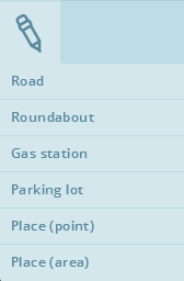
Hover the cursor over the large + icon at the top of the screen in the toolbar and click Road. You can also use the keyboard shortcut, which is the letter i, for Insert. Move the cursor to the location you want to start drawing the road. This can be an empty location, or it can be on an existing segment where you want the intersection with this new road. The cursor has a small blue circle to indicate it is in drawing mode.
When you hover over an existing segment, it will highlight, showing that if you click there, a junction will be automatically added.
Move your mouse along the path of the road, following the aerial view or GPS points for the new road. Every time you click, a geometry node is added, aligning your new road with your cursor movement. When you reach the end location for the new road, double-click the mouse. You will exit drawing mode, and the new road will display in orange to signify that it is unsaved. Don't worry if you made a mistake in drawing the shape of the road. Just click on the segment again and you can add, remove or reposition geometry nodes. If you want to remove the road just drawn, you can press the ESC key on the keyboard before you exit drawing mode.
In our example, there is another road in this same view which is missing. We can add another road to the map without saving the first one. The next image shows the second road already added, and auto-junctioned to the first segment we just created.
At this point, you can save the newly added roads if you wish. However, the process of properly adding the roads is not complete. All new roads are set as 1-way, with no associated city and no street name. Adding these details to the road is required before they will show up in the Waze client app.
Note: When creating special roads like roundabouts and loops, be sure to follow the special considerations for those roads in those linked sections.
Confirm the road by updating details
New roads will not be displayed on the Waze app until they are confirmed, meaning an editor sets the country, state (for the US), city and street name. In the map editor, unconfirmed roads are displayed in red. Unconfirmed roads may be roads drawn in the editor, or paved (recorded) from the app.
To confirm a road, select one or more segments with the mouse. A best practice is to select segments with the same road name, since you can only add one name at a time. Notice below that for the first road, there are now two, one-way segments. That is because the second road we added has split the original road into two segments. Sometimes it is more efficient to confirm a single road before adding other intersecting roads, because there is a bug in the editor which forces you to re-enter state and country data that has already been applied.
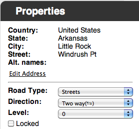
To edit the address details, click the Edit Address link under the Properties tab. This will enable editing of the fields above it. When multiple segments are selected, you need to select Country (and State, where enabled) then enter the city and street name information. If this segment is outside a municipality, use the "No City" check box. For streets with no name, such as private roads or parking lot roads, use the "No Name" check box.
For roundabouts, do not enter a street name. Leave it as "no city" to allow proper navigation routing through the roundabout.
When complete, click the Apply button, then set the correct Road Type, Direction and Level. For neighborhood streets in these examples, Street is appropriate, they are 2-way streets and they have no roads above or below them, so Level 0 is correct.
- Please be aware the the directionality type 'No Entrance' does not prevent Waze from routing onto a road. 'No Entrance' really means 'Undefined'. When the direction is set to 'No Entrance' Waze will automatically adjust the directionality of the road as Wazers drive it. This is the initial directionality of all roads after a base map import. In addition, the locked checkbox does not prevent the directionality from changing on 'No Entrance' roads as Wazers drive it.
You may choose to save now, but there is one more step before we can call this process complete: setting the allowed turns.
Set allowed turns (connections)
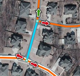
We've added our roads and confirmed them, but we haven't set the legal directions to and from this segment. In the real world, there are barriers and signs which prevent travel in a certain direction, even though the roads connect to each other. In our suburban neighborhood example, none of these blockages exist, but our screenshot shows red arrows, meaning that Waze won't navigate that direction from the selected segment. Click on the red arrows to turn them green, and permit navigation in that direction. This needs to be done for each segment that is added to the map, as the default setting after connecting a new segment is to disallow all turns to the new segment.
In situations where not all turns are allowed, click on the arrow to turn it red for the disallowed direction from that segment.

If all turns are allowed at a junction, the fastest way to enable all turns is by selecting the junction and not the individual segments. Select the junction and it will turn from an orange circle to a red circle with a white border. Note that if you have already selected a segment connected to that junction, click elsewhere on the map, or hit the ESC key to deselect that segment before you can select the junction.
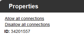
The Properties drawer will show you action links for the selected junction. Depending on the current state of the junction, one or both of the links Allow all connections or Disallow all connections links will appear. For example, if all connections are currently allowed, then only the Disallow all connections link will appear.
To enable all turns at an intersection, click the Allow all connections link for the junction. Alternately you can use the keyboard shortcut W to allow all connections and the shortcut Q to disallow all connections. A best practice when allowing all turns on a junction is to disallow all turns first, as it cleans up some legacy problems with the map.
Other helpful turn arrow keyboard shortcuts are:
- Shift+z - Toggles between: 1) showing the enabled and restricted turn arrows for the selected segment, and 2) showing all restricted turns (red arrows only) for every junction on the visible map (up to zoom level 4 or 500 ft in the lower left map legend).
- a - Toggles between making the turn restriction arrows directly selectable (opaque) or transparent. Transparency enables selecting objects below the arrow on the map.
- s - Toggles between separating turn arrows so they don't overlap or leaving them overlapping. This can also be used to refresh the screen when you have toggled visibility for all restricted turns, and you are modifying turn restrictions.
To see all keyboard shortcuts, press the ? on the keyboard.
Save
If you have saved your progress or not, click the Save button (or use the Ctrl + s keyboard shortcut) to send all of your updates to the Waze servers for processing. After the save is complete, and if there are no errors, you will be presented with a view of the final product of this process:
It is a good practice to save your changes often, and certainly when you get more than 10 unsaved changes pending. Sometimes you may run into a save error that you cannot determine what is wrong, and you have to undo many prior edits. Sometimes you will have to undo all the way back to your first edit. Saving regularly limits chances of lost work in case of unresolvable errors.
Editing existing roads
Editing an existing road segment is not very different from creating a new road. Once a road is drawn from scratch, before it is saved, all of the editing functions described here work.
Adjusting road geometry (nodes)
Adjusting road geometry is changing the shape or appearance of a road segment. Real-world roads may be realigned, or mapped roads may be in the wrong place because the data from the basemap import was wrong. Sometimes we need to realign roads to improve navigation or spoken instructions in the Waze mobile app.
The instructions here, while written for an existing road segment, also apply to a new road segment you just created, but have not yet saved. The editor treats them the same.
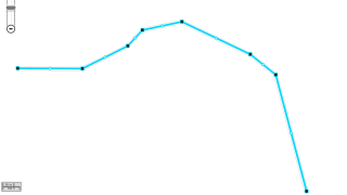
To start adjusting the geometry of a segment, click on it. When you hover over the highlighted segment, geometry nodes (black squares) and internodes (white circles) will display along the segment. Both of these are draggable so that you can reposition them wherever you need. When you drag an internode from its default position half-way between two nodes, it will turn into a node.
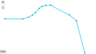
To delete a node, hover the cursor over a node and hit the d key on the keyboard. This only works with nodes, not internodes. When you have a long, straight stretch of road, and there are nodes located along it's length, delete these nodes. It simplifies the road segment if you have to tweak it, lightens the load on the database, and makes it easier to display on the Waze client app.
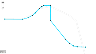
When your moves are complete, save, and the segment will appear in the map with the new geometry.
To see these operations in action, you can watch a video of adjusting segment geometry.
Fix the end-node on cul-de-sacs and dead-ends
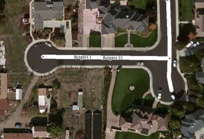
In order for the Waze Application to properly route from a location on a cul-de-sac or dead-end road, the end of the last segment must have an end-node. Without this end-node, Waze will give the instruction Proceed to Highlighted Route.
In the image to the right you can see a small blue diamond at the end of the long court, and no blue diamond at the end of the short court. The short court is missing an end-node at the end of the segment.

When you select each segment, putting them into an edit mode, you can see the difference between the two roads. The long court has the end-node (small white circle) and the short court has a geometry node (large black square) at the end of the segment.
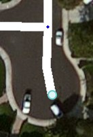
To add an end-node to the short court, a temporary road segment must be added to the current road. Start by not having the road selected (make sure it is white by clicking elsewhere on the map). Hover the cursor over the large + icon at the top of the screen in the toolbar and click Road. You can also use the keyboard shortcut which is the letter i, for Insert. Position the cursor so the blue circle appears at the end of the segment and Left-click the mouse to start the road.
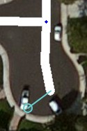
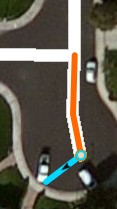
Click some distance away from the end of the current road and double click to end road creation. Select the newly created segment and press the Delete key or the Trash Can icon from the toolbar.
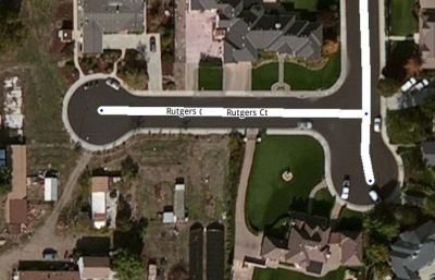
Save the changes and the result will show the small court now has the proper end-node showing as a small blue diamond (when not being edited or selected).
Note that most cul-de-sac should not terminate in a roundabout or loop, but as a dead end as drawn here.
Junctions
Before making any change to a junction, be sure to review the Junction Style Guide for information on the best practices for creating junctions. There are many times when a junction may be drawn in a way that does not seem logical, but it is very important to the navigation engine in Waze.
Moving junctions
Moving a junction is as simple as dragging the junction to another location, however there are geometry nodes (the black squares seen when editing a segment) that may also need to be adjusted.
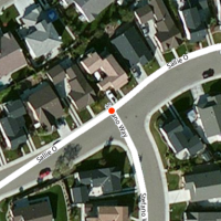
First use the mouse to select the intersection of the road segments. This will put a red dot, circled in white, on the junction. This indicates you will move all the segments connected to this junction. Note that if the red dot appears transparent, it means that one of the attached road segments is locked above your editing level, and the junction cannot be moved by you. Release the mouse button and move the mouse away until the cursor appears as a 4-way crossed arrow ![]() .
.

With the cursor as a crossed arrow, select the junction again and drag it to the desired location. The harsh angles in the segments in this example are caused by the geometry nodes and will need to be adjusted. It is important to position the junction in a location that is not on top of a segment. This makes it difficult to adjust the geometry nodes, and in some cases will tell the editor to merge junctions, if one is present below the junction you are moving.

The black geometry nodes can be moved, removed, or added as explained in detail above. Adjust them to align with the aerial views or the GPS tracks.
Removing junctions with only two segments
There are times when only two segments are linked to each other with a junction. In general this is not a problem, but it can slow down editing and it may be the source of incorrect turn restrictions and bad routing. So the best practice is to delete these junctions when found. However, it is very important to study the two segments before merging, to ensure the junction is not there for a purpose.
| Legitimate Reasons for Two-segment Junctions |
|---|
| One of the segment properties is different at that point, i.e., city name changes, road name changes, road type changes, road direction changes |
| The segments are part of a loop road and require the extra junction to allow the Waze routing engine to properly navigate through the loop. |
Once you are certain there is no reason to have the extra junction, there are three methods to remove it. One method highlights the junction and deletes it, one highlights the two segments and bridges them together, and the last method will drag one junction on top of the other junction.
Delete key or trash can icon
This method is the preferred method, because it enables the WME to alert you when there are legitimate differences between the segments. With the mouse select the junction point between the two segments. Look for the trash can icon at the upper right corner of the WME screen. If it appears press it to remove the junction. It will place a geometry node at that point automatically. If you need to remove the node, you can do so by highlighting the segment and hovering the mouse over the point of the prior junction. It will display the node and you can press the d key to remove that node if necessary.
If the trash can icon does not appear, something about those two segments are different possibly including the city name, street name, or direction of travel.
Bridge segments
This method is less desirable because when used it causes the road level of the segment to increase by one.

With the mouse, select one of the segments. Then, while holding down the multi-select key (Control for Windows/Linux and Command for Mac) select the second segment. If the two segments have the same properties including direction, a small bridge icon will appear above the junction. Click the bridge to merge the two segments, eliminating the junction between them. A geometry node will be placed where the junction was previously located. To remove the node (if necessary), select the segment and hover the mouse near the old junction. The geometry node should be displayed. Then, press the d key to remove the unwanted node.
When the segments are different, the bridge icon will not appear at the junction.
Drag together
This method will eliminate the road segment between two junctions. It will ignore any differences between the central segment and the segments on either side of the junctions to be merged. It should only be used when you are certain there is no legitimate reason for the central segment to be different.


With the mouse, select one of the junctions to be merged, turning it into a red circle with a white ring around it. Next, drag it toward the other junction while watching for any acute angles in the segment between them. If angles appear, it means there are geometry nodes between the two junctions, and they need to be removed before you can attempt the merger. If there are no geometry nodes between them, simply slide the red junction on top of the second (target) junction and they will merge. Note that turn restrictions previously set on either junction may be overwritten, so review them to insure they are set correctly using the procedure above.
Allow/Disallow connections
Changing the allowed and disallowed turns in a junction follows the same procedure for controlling them when updating a road segment described above.
(Re)Moving a road from a junction
Updating road details
The details of a road can be entered as discussed with regard to confirming the details of a new road above. The procedure is the same for updating the details of an existing road segment.
To update details, first, select the segment(s) you need to update. Click on the segment and the segment will turn blue.

Multiple segments may be selected by holding down the modifier key and clicking additional segments. The modifier key for Mac is the command key, for Windows the control key and for Linux the control key. Each selected segment will turn blue.

Once selected, if the General tab is visible on the left side of the editor.
Address Properties
At the top of the properties toolbox are the address fields. The address fields include the street name, city name, State (currently only in the United States) and country. To edit the address details, click the Edit button. This will enable editing of fields above it.
The Country (and State) fields may be updated by selecting a different country (or state) from the dropdown selections. Selections will only be provided for countries (or states) that are present on other nearby road segments.
The city and street names may be updated by typing a new name. See Naming for guidance on choosing the correct street name. As a name is typed, Waze provides a list of similar names. These similar entries can be selected by clicking them. If the segment is in a location outside a city, the "None" check box should be selected and the city name will be blank. If the road does not have a name, the "None" check box should be selected and street name will be blank. Entries must be present for each address property. To eliminate a city name or street name the appropriate "None" boxes must be checked. When complete, click the Apply button. If no changes are to be made, click the Cancel button.
Alternate street names can be added or deleted. To delete an alternate street name click the ![]() next to the alternate name to be deleted. To add an alternate street name click the "Add alternate name" link and type in the alternate city name and alternate street name.
next to the alternate name to be deleted. To add an alternate street name click the "Add alternate name" link and type in the alternate city name and alternate street name.
If the above Address Properties are not set for a segment, the road will display as a red line in the editing map only and it may not appear in the Waze client app after the next update. This process is part of the road verification process. When the Waze client app uses the pave option, the road is created in the edited Waze map only. That Wazer or another Wazer who is editing the map in that area must set these properties in this section in order for the road to be seen in the client.
Road Properties
Below the address properties on the General Tab are the road segment properties.
Road Type
The road type is changed by selecting the appropriate road type from the drop down box.

See the Map_Legend for further guidance on selecting the correct road type.
Road Direction
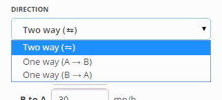
The direction of the road is changed by selecting the appropriate direction from the drop down box.
If traffic may travel both ways on the road, select "Two way." If traffic may travel only one-way on the road in the direction from the ![]() toward the
toward the ![]() select "One way (A→B)." If traffic may travel only one-way on the road in the direction from the
select "One way (A→B)." If traffic may travel only one-way on the road in the direction from the ![]() toward the
toward the ![]() select "One way (B→A)."
select "One way (B→A)."
After the road properties are saved, the direction is indicated by blue chevrons on the road.
Base mapped roads are originally assigned the direction of unknown. When the direction is set to unknown Waze will automatically adjust the directionality of the road as Wazers drive it. When editing make every effort to determine the correct direction of the road and choose either "Two way" or the appropriate "One way" direction.
Road Level
The Road Level should be changed where one road passes over another. By default, the Level of a segment is 0 (zero). When two segments overlap but do not actually connect in the real world, the value of Level for each segment must be different. This ensures that the Waze problem detection system doesn't flag the spot where two segments overlap as a location where a junction might be needed.
The visual representation of the relative Road Levels is different when viewed in the Waze Map Editor (WME) and the Client application.
1. The Client App will display segment levels based on the road type only, meaning Freeways are always on top, Major Highways are next, followed by Minor Highways, Ramps next, Primary Streets below all those, and finally Streets are at the bottom. This is the same order seen when setting the road type in the editor.
2. The WME uses the Road Level setting to display the relative level of the road. It displays the road with the highest "level" number at the top of the visual stack and works its way down as would be expected.
Although the client application does not benefit from the Road Level setting, it is recommended to set the Road Level relative to the physical mapping in the real world to enable possible future Client application updates to show the same visual representation as the WME.
See Bridges for more information on levels.
Locked Box
The segment is locked by checking the locked check box. For information on the effect of checking the locked box see Locked Roads.
Changing turn restrictions
Each intersection of two or more segments keeps track of the allowed directions you can turn from one segment to another. Changing these turn restrictions follows the same procedure as outlined above in the section on Set allowed turns.
Separator line (disabled)
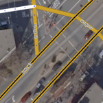
The original map editor before the Waze Map Editor had the ability to add a black separator line down the middle of a road segment. It caused difficulty with map editing and was removed as a feature from the updated WME. The Waze developers will eventually have all of the current separator lines removed from the map. Until that time they should be ignored.
Roundabouts
See Creating and Editing a roundabout for guidance on roundabouts or traffic circles.
