Sin resumen de edición |
Sin resumen de edición |
||
| Línea 3: | Línea 3: | ||
{{ReturnTo | Editor_de_Mapas_Waze | Editor de Mapas}} | {{ReturnTo | Editor_de_Mapas_Waze | Editor de Mapas}} | ||
== Iniciando la sesión == | == Iniciando la sesión == | ||
* Se accede al editor WME desde la página http://www.waze.com/editor | * Se accede al editor WME desde la página http://www.waze.com/editor | ||
| Línea 46: | Línea 43: | ||
=== | === Eliminar un punto de unión === | ||
Un punto de unión es un pequeño círculo blanco con contorno negro que conecta dos o más segmentos. Los puntos de unión con solo dos segmentos pueden parecer innecesarios, pero puede que en realidad tengan un propósito. Antes de eliminar un punto de unión de dos segmentos, asegurate de que esta unión no está presente por una de estas razones: | |||
* | * Un cambio en el nombre de la calle, la ciudad, el estado o el país. | ||
* | * Un cambio en la elevación de la vía que permite complejos [[Best_map_editing_practice#Overpasses_.26_Underpasses|overpasses and underpasses]]. | ||
* | * Parete de una [[Junction_Style_Guide#Loops|loop road]] que previene errores de ruta. | ||
Si estás seguro de que el punto de unión no está por uno de los casos anteriores, lo puedes eliminar siguiendo uno de estos dos métodos: | |||
# | # Haz clic en el punto de unión, veras que cambia de color a azul con contorno blanco, lo que significa que lo tienes seleccionado. Haz clic en el icono basurero, o usa el atajo de teclado "Suprimir". Esto convierte el punto de unión en un nodo geométrico y combina los dos segmentos. Solo un máximo de dos segmentos deben estar conectados a un punto de unión para que se pueda borrar. | ||
# Select segments on either side of the junction, and click the Bridge icon which appears over the junction. <b>Note that this will also increase the level of the segments by 1, so this method is best used only when replacing an inadvertent junction with an overpass.</b> | # Select segments on either side of the junction, and click the Bridge icon which appears over the junction. <b>Note that this will also increase the level of the segments by 1, so this method is best used only when replacing an inadvertent junction with an overpass.</b> | ||
| Línea 288: | Línea 285: | ||
{{ReturnTo | Editor_de_Mapas_Waze | Editor de Mapas}} | {{ReturnTo | Editor_de_Mapas_Waze | Editor de Mapas}} | ||
[[Category:Spain]] | [[Category:Spain]] | ||
Revisión del 16:54 24 may 2020

|
Estamos trabajando en esta página, por lo que pueden haber enlaces perdidos. Gracias por vuestra paciencia ;)
|
Iniciando la sesión
- Se accede al editor WME desde la página http://www.waze.com/editor
Para iniciar sesión, usa el mismo usuario y contraseña que en la aplicación de cliente de Waze y en el resto del sitio web de Waze. No olvides seleccionar el servidor adecuado para la edición de mapas. Se puede modificar desde configuración, en el panel de navegación de la izquierda. En Europa usamos el entorno 'mundo'. Si situas el mapa en Europa y el entorno fuera otro, Israel o Norteamérica, el propio navegador te mostrará un mensaje de advertencia para que modifiques el servidor.
Funciones comunes
All of the following sections use terms that are defined in the glossary for your clarification.
Capas
Muestra y oculta las capas pulsando en el icono en el lado derecho de la vista de mapa.
Para obtener más detalles sobre las capas disponibles, consulta en Layers section of Map Editing Interface and Controls
Crear una carretera (segmento)
- Coloca el cursor del ratón sobre el icono Vía en la parte superior del editor y selecciona el tipo de vía que quieras añadir. Vía para cualquier tipo de vía por la que circulen coches, y Peatonal para aquellas por las que no circulen vehículos.
- Haz clic en el punto del mapa donde quieras que comience el segmento.
- Mueve el cursor a lo largo del trazado. Ve haciendo clic si necesitas añadir nodos de geometría para definir la forma.
- Haz doble clic en el punto final del segmento.
- Presionando ESC se abortará la creación del segmento.
- Puede parecer una obviedad, pero asegurate de que el segmento existe en la realidad antes de crearlo.
- Cada segmento que se añada debe tener información sobre el País, Estado, Ciudad y calle. Si falta alguno de estos campos, el segmento aparecerá silueteado en rojo para indicar que no está completo. Si no debe tener nombre de ciudad o de calle, se debe marcar la casilla a ninguna.
Borrar un segmento
- Haz clic sobre el segmento
- Clic en el icono Basurero
in la barra de herramientas, o pulsar suprimir en el teclado.
Puedes seleccionar y borrar varios segmentos a la vez, pero en ese caso no se puede usar la tecla suprimir. Tendrás que pulsar el icono basurero y después confirmar que quieres borrar los segmentos.
Conectar segmentos
Cuando se dibujan nuevos segmentos, o se desplazan alrededor, el editor los unirá automáticamente.
- Para vías nuevas, si empiezas y/o acabas la vía sobre un segmento ya existente, automáticamente se crea un punto de unión.
- Para vías ya existentes, si movemos el extremo de un segmento hasta otro ya existente, se crea un punto de unión.
- Si mueves un punto de unión hacia un segmento existente, esa unión será ahora parte de ese segmento y todas las vías previamente conectadas a ese segmento quedarán unidas juntas.
Asegurate de comprobar las restricciones de giro para tus recién creadas conexiones.
Eliminar un punto de unión
Un punto de unión es un pequeño círculo blanco con contorno negro que conecta dos o más segmentos. Los puntos de unión con solo dos segmentos pueden parecer innecesarios, pero puede que en realidad tengan un propósito. Antes de eliminar un punto de unión de dos segmentos, asegurate de que esta unión no está presente por una de estas razones:
- Un cambio en el nombre de la calle, la ciudad, el estado o el país.
- Un cambio en la elevación de la vía que permite complejos overpasses and underpasses.
- Parete de una loop road que previene errores de ruta.
Si estás seguro de que el punto de unión no está por uno de los casos anteriores, lo puedes eliminar siguiendo uno de estos dos métodos:
- Haz clic en el punto de unión, veras que cambia de color a azul con contorno blanco, lo que significa que lo tienes seleccionado. Haz clic en el icono basurero, o usa el atajo de teclado "Suprimir". Esto convierte el punto de unión en un nodo geométrico y combina los dos segmentos. Solo un máximo de dos segmentos deben estar conectados a un punto de unión para que se pueda borrar.
- Select segments on either side of the junction, and click the Bridge icon which appears over the junction. Note that this will also increase the level of the segments by 1, so this method is best used only when replacing an inadvertent junction with an overpass.
Remember that all elements of the road name, city, state (where applicable) and country must match for either of these two options to work.
You will also find additional information related specifically to Overpasses, Underpasses and Bridges in that section.
Loop roads
When drawing a road which connects to the same segment at both ends, be sure to check that there are three segments in the loop you are creating. To create the proper loop:
- Draw your road starting from one side of the loop

- Follow the road to an intuitive junction point
- Draw a new segment starting at the finish point of the first
- Connect the second segment to the finish point of the original road segment
- Count the segments in your loop, you need a minimum of three.

Additional Note: When a segment is drawn, it cannot create two nodes on the same segment at the same time. The 'A' end of the segment will appear to be connected to the segment, but it will not be connected, and this node will need to be dragged over to the existing segment to be connected, which will cut it again. A way around this is to draw the road as two successive segments. An example of this is shown to the right.
For more information on this topic see the article Loops in the Junction Style Guide.
Junction arrows
Note: Previously, "Junction Arrows" were called Turn Restrictions, abbreviated by TRs. However, the term has been replaced because of the disambiguation process.
See the Partial restrictions page for details of how to set up time-based turn or time-based segment restrictions.
Helpful turn restriction tips are covered below.

|
Be sure to review the information on soft and hard turn restrictions before reviewing the information below.
|
Standard turns
Set by selecting a segment which will allow you to see the connectivity arrows and modify these allowed turns at each end of the segment.

In General:
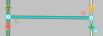
- A green arrow means Allowed
- A yellow arrow with a clock means scheduled or vehicle-type based
- A red arrow with the circle-slash icon means Restricted
- Clicking an arrow toggles between Allowed and Restricted (or, if partial restrictions are in effect, between Partial and Full Restricted). Each arrow must be set correctly for Waze to route correctly.

|
The slashed-circle icon for Restricted and clock icon for Partial turn restrictions were put in place to allow editors who have various forms of color blindness to be able to differentiate between the three different types of turn arrows.
|
| Turn related icons | |
| Icon | Description |
|---|---|
| A green arrow indicates that travel is allowed from the selected segment in the direction of the arrow. | |
| When you hover the mouse over an allowed turn arrow, a small clock icon appears, which, when clicked on, allows you to set scheduled turn restrictions and vehicle type restrictions (collectively, "partial restrictions"). | |
| A red arrow with the slashed-circle icon indicates that travel is not allowed (is restricted) from the selected segment in the direction of the arrow. | |
| A yellow arrow with a clock icon indicates the presence of scheduled (time-based) turn restrictions or vehicle-type based restrictions. | |
| When you hover the mouse over a yellow arrow, a 2nd small clock icon appears bordered in blue, which, when clicked on, allows you to modify the turn's partial restrictions. | |
| The Purple question mark shows that all the turns at that end of the segment have not been locked (confirmed) by an editor. Click any turn arrow to lock them. A purple question mark at the end of a segment is also referred to as a Soft Turn. Locking it, removing the purple question mark, makes it a Hard Turn. | |
| A curved green arrow indicates that a u-turn is allowed in the manner and direction indicated by the arrow at that end of the segment. | |
| When you hover the mouse over an allowed u-turn arrow, a small clock icon appears, which, when clicked on, allowed you to set scheduled u-turn restrictions, as well as vehicle type restrictions on the U-turn. | |
| A curved red arrow with the slashed-circle icon indicates that a u-turn is not allowed (is restricted) in the manner and direction indicated by the arrow at that end of the segment. | |
| A curved yellow arrow with a clock icon indicates the presence of scheduled (time-based) turn restrictions for the direction indicated by the arrow at that end of the segment. | |
Where the arrows appear depends on the road. One-way roads will only have arrows at the end, and roads with unknown directionality will have no connectivity arrows at all.


U-turns
Two-way segments will also show the small U-turn arrow icon at both ends of the segment. This is used, as its name suggests, to prevent/enable Waze to use a segment end node as a U-turn, in case of necessity. When setting the U-turn arrow to green, make sure that U-turn is possible AND LEGAL in real life. In any other case, set the arrow to red for drivers' security. Just as with other turn restrictions, allowed U-turns must be set on a per-segment-per-end-node basis.
Plantilla:As of, Waze is able to provide U-turns in a route where the U-turn arrow is enabled, or where the turn angle is greater than 170°, and will give a "make a U-turn" instruction. If the current U-turn arrow setting on the segment could prevent Waze from giving the best route, or if it causes instructions to make an illegal turn, it should be fixed.
- Some examples where allowing a U-turn can allow Waze to find a better route for a Wazer include:
- When the drive begins with the car headed the wrong way for the best route, and when a Wazer has made an incorrect turn during a drive.
- When reversing course is quicker than taking a long detour, allowing the U-turn enables Waze to find a better route.
U-turn laws are sometimes different in different parts of a country. Always check the local laws before changing U-turns. Check all local wiki pages or talk to a Country Manager, or State Manager. Local knowledge may be needed to be sure whether a specific U-turn is safe and legal.
U-turns at the end of dead-end-streets
Plantilla:As of, U-turns at dead ends or cul-de-sacs, no longer need to be adjusted in a particular way. WME no longer provides a link to adjust it.
Junction arrow tips
- Press s to separate overlapping arrows.
- Press a to toggle connection arrows transparent or opaque so you can see beneath them and click items under them
If an intersection should not have any restricted turns, you can easily enable all turns. Initial junction arrows on roads are set automatically by the Waze routing engine. Automatically set arrows can be altered by the routing engine, but manually set arrows cannot. Unfortunately, both automatic and manually set restricted turns are represented by red arrows and cannot be distinguished. Currently, when you use the option to enable all turns, it will not fully change the routing from automatic to manual for the turns. To clear the automatic routing for an intersection, start by selecting the junction with the mouse. Then you can choose between mouse clicks or keyboard shortcuts. With the mouse, in the properties toolbox, click the link to "Disallow all connections" and then "Allow all connections". Alternately you can use the keyboard shortcuts by pressing the letter 'q' to disallow all connections followed by 'w' to allow all connections (see keyboard shortcuts).
To see all currently restricted turns for all intersections on the map press 'Shift+z', which will toggle between the junction arrows for one selected segment, and the turn restrictions for all intersections.
See the section set allowed turns for more information.
Selecting multiple segments
Some edits require that you select two or more segments of road. Other times, you want to apply the same change to multiple segments. In the default select mode, you must use the modifier key below:
- Windows: ctrl+click
- Mac: ⌘ Command+click
- Linux: ctrl+click
When in multi-select mode (keyboard shortcut m), you do not have to use the modifier key.
This feature is useful for changing one particular element of multiple segments, or when using the permalink feature.
Selecting segments between two segments
To select segments between two segments, follow this procedure
- Select a segment at one end of the desired range
- Use the modifier alt+click to select a second segment at the other end of the range
WME will select all the segments in between the first segment and the second segment.
- The route followed between the two segments is the route with the shortest number of segments.
- The route is limited to 25 or fewer segments.
This feature is helpful for applying closures or changing attributes for several segments.
Selecting segments in a box
To select all segments within a box, use this sequence to define the area desired.
- ctrl+⇧ Shift+click (MAC users:⌘ Command+⇧ Shift+click) and then drag the cursor while holding the mouse button to form a box
- When the box includes the desired segments, release the mouse button and all the segments in the box are selected.
Use ctrl+click to select any missing segments or to remove any undesired segments.
Selecting entire street
- Select a segment
- In the tabs area, click the Select entire street button, or use the keyboard shortcut Ctrl+A
- The selection can be edited as a group.
- The selection will include any segments with same primary road name (including city and state) as the initially selected segment and does not require them to be connected.
- Road types do not need to match.
- Select entire street will not work with unnamed segments.
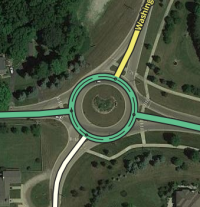
Creating a roundabout

See the article Creating and editing a roundabout for more details on this topic.
Use these steps to create a roundabout:
- Hover over the
 at the right side of the toolbar click on Roundabout.
 - Click the map at the center of the roundabout.
- Move the mouse outward to the correct size of the roundabout.
- Click to finish.
Notes:
- There must be roads that touch the roundabout when you click to finish, otherwise no roundabout will be created.
- Roundabout drawing is circular by default. Ellipse drawing can be enabled by holding down the Shift key while adjusting the roundabout size.
- Roundabouts can be created over existing junctions and segments. Any roads within the shape of the roundabout will be truncated, and any junctions within the roundabout shape are deleted.
- To delete a roundabout, you must delete ALL segments of the roundabout. You cannot save your work without deleting all segments of the roundabout. When saved, the roundabout node will also be deleted.
- Roundabouts cannot be created over a maximum of Roundabouts/Maximum in diameter.
Creating a Place (landmark)

|
WME is undergoing changes. These instructions might not be completely correct. Please see Draw Places Menu
|
- First, read the Places page to determine whether you should create an Area or Point Place
- Hover over the
 at the right side of the toolbar click on Place (area) or Place (point)
 - For a Point Place, click directly on the location which should be the stop-point for navigation
- For an Area Place:
- Click a point of the map on the edge of the area
- Move the cursor along the path and click to add a geometry node to define the shape
- Shift+click (or double click) at the last point to stop drawing and complete the shape
- Select the new landmark (if it isn't already) and define the category and all other information including multiple categories, and FULL ADDRESS. Full details are in the Places wiki page.
Bridge junction
- The properties of the segments to be bridged must be identical or you will not see the bridge icon
- Bridging automatically increases the level of the new merged segment by 1 more than the highest level of the two segments. You can change it, of course, if it needs to be a different level.
Generally, if two segments can be joined, if you select the junction you can press the trash can icon to have them join as well. If the trash can icon does not appear, the segments are different in some way and that might be the reason there is a junction in the first place.
- For more detail, see Overpasses, Underpasses and Bridges.
Overlapping road junction
Two roads set to the same level which cross each other can be joined by an intersection easily. This is useful if you draw several new roads for a neighborhood by drawing segments from end-to-end and allowing new segments to cross each other. Once drawn, you can junction them using this method.
Both roads must be set to the same level. You can often use this method with unconfirmed (red) roads, but sometimes the editor will refuse to do this process until the roads are confirmed. Additionally, changing zoom level sometimes helps to get the sometimes-stubborn junction creator icon to appear.
- Select both segments
- Click the
 which should appear above the intersection
- Note: The sign won't appear if the roads cross each other multiple times
- A junction is added
Cutting a segment
To add a junction somewhere in the middle of an existing segment, create a new segment that intersects the existing segment. Begin the new segment on the existing segment at the desired point. Now simply end the new segment somewhere nearby without connecting to any other segment. With the newly drawn segment still highlighted, delete the new segment. The new junction in the existing segment will remain.
Joining junctions
When joining or removing a junction, there are a few considerations that should be taken into account. Please review the more detailed article on junction removal.
Disconnecting a road
Select the segment. Drag the end you want to disconnect away from the junction.
Solve map problems
Map Problems in Waze Map Editor
