The following article contains key information on properly creating junctions and the roadways between them. Be sure to review it in its entirety before editing the map.
Simple is better
When representing junctions (a.k.a. intersections, cross roads, corners, etc.) between roads, we sometimes have to blur the lines between the physical and logical worlds. The primary goal should be to represent things as simply as possible and only introduce complexity to deal with an issue.
The Basics ← START HERE
What is a Junction?
A junction is made up of three things:
- At least two roads
- One or more places these roads meet (a junction node)
- Turns allowed or restricted at those junction nodes
If you do not know how to create and modify roads, junctions, or turns, please read the Map Editing Quick-start Guide.
Diverging Roads
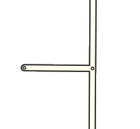
Let's start with the basic case of a road branching off. The branch road will normally meet the main road at nearly a 90 degree angle. This is the simplest situation to map, as the physical and logical views of the roads match up well.
You will find roads that meet at odd angles as well. Even in urban areas with rigid grids, you will often find a road that existed prior to the establishment of the grid, which cuts through town at strange angles. The initial urge will be to represent the junction as it is in the physical world - two lines running into each other at a sharp angle.
But there are issues with this method. Depending on the angle, the client may give a "Keep Right" instruction to the driver when a "Turn Right" instruction is more appropriate. In some cases, no instruction will be given at all. In the worst case, the routing engine may determine that it isn't possible to make a very sharp turn angle and not suggest the turn at all. (In the example image, heading south, then turning left, to head east.)
To eliminate ambiguity, we need to map the junction from a logical point of view. Since we want to be given basic "Turn Left" and "Turn Right" instructions, we have to tweak it so it resembles a basic 90 degree intersection. But how do we do that when the roads don't actually diverge at 90 degrees? We add some geometry nodes to make the branch road leave the main road at close to 90 degrees, then we gradually curve the road to match the true departure angle.
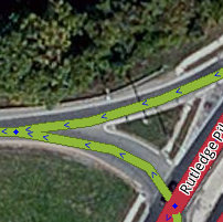
Now we have a junction that logically works like a basic 90 degree junction but it also fits the reality of the physical world. Here is a completed real world example:
A ramp from a highway is another good example where additional geometry nodes are helpful. Especially since most ramps diverge at a very small angle from the road.
The drawback in this case (which also exists for the side road example above) is it may be hard to see and click on the turn restriction arrows in the editor.
But if we add one more geometry node to make the departure angle at the junction closer to 20 or 30 degrees (Why those angles? See the discussion on Geometry and turn instructions later in the page for details)...
...now the arrows are visible and accessible. Note that you can also press 's' in the editor to spread or separate the arrows at a junction, if you still have difficulty clicking on an arrow. (see Editor Keyboard Shortcuts for more tips.)
Now we have made sure this junction behaves as we would expect. Because we have used a specific angle, we can clearly see and access the turn restriction arrows, and we have fidelity with the layout of the road system.
Crossing Roads
We can apply the above approaches to a four-way junction. Again we can expect to see angles close to 90 degrees.
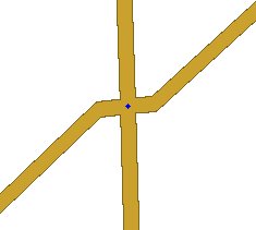
And if we have that street cutting across town at an odd angle, we want to avoid the odd angle at the junction.
We want to use geometry nodes to bring the actual junction close to 90 degrees. You can zoom in and add a single geometry node on each side. This will give the proper angle but make it virtually invisible to users so it looks just like the physical world.
The above image is what you would see zoomed in as close as possible. Zoomed back out, it looks just like the image showing the junction without any geometry nodes.
And here is a real world example at a zoom level where you can still see the geometry adjustment we added:
With that adjustment in place, the junction will produce predictable turn left/right navigation instructions while the roads still appear to meet at the real-world angle.
Controlling Turn Instructions
Before going further, make sure you understand the mechanics of turn restrictions in the Map Editor. If turns are not properly enabled and restricted, you will never get the proper navigation instructions.
In the Basics section above, we touched on how to ensure a "Turn left/right" instruction would be given over a "Keep left/right" instruction. Details of the mechanics behind this can be found on the How Waze determines turn / keep / exit maneuvers page, but a summary is provided in the sections below.
Geometry
If all junctions you edit follow a few basic forms, it will be much easier to predict the navigation behavior of an individual junction without getting into the details of the back-end algorithms.
- Approximately 90 degree departure angle = Turn instruction
- Between 20 and 30 degree departure angle = Keep Right / Keep Left instruction (or Exit Right / Exit Left for Ramps)
- Approximately 0 degree departure angle = no navigation instruction
These angles allow us to clearly depict the desired result (turn vs. keep) while staying away from the angles that cause uncertain decisions from the routing algorithms. For example, since 45 degrees is a tipping point for the algorithms, a 44.5 degree angle will behave very differently than a 45.5 degree angle, although they will look identical to the eye.
Similarly, if we have a road split at a Y and we want to be clear about which is "straight" and which bears off to the side, having one branch at zero degrees and the other branch at 5 degrees isn't clear and obvious; but "straight" would be much more apparent if the angles were zero degrees vs. 20 degrees. Since most of us will not have a protractor handy when we are editing, it is best to simply avoid situations where exactness matters.
This knowledge allows us to control how a junction behaves by modifying a single geometry node in most cases. This is often useful for At-Grade Connectors where sometimes we prefer a "Keep right/left" and other times a "Turn right/left" would be more appropriate.
If we keep the departure angle in the 20 to 30 degree range, we would get a "Keep Right" to follow the curved one-way connector:
But if we move one geometry node to create a 90 degree angle, we would receive a "Turn Right" instruction.
Similar rules apply for the end of that segment as well. If we have a 20 to 30 degree angle as pictured above, there will be no turn instruction, as traffic just smoothly slides into the cross street. But if we make the end of the segment close to a 90 degree angle, then there would be a turn right instruction for the driver.
Segment Naming and Type
The names and road types of the attached segments affect the routing algorithms, in addition to the geometry of the road segments,
A rule of thumb is if you want a turn to be announced, having a name difference between segments will improve the chances (but not guarantee) that it will happen. In the case of the At-Grade Connector example above, the connector should either have a different name than the road it is leaving, or no name at all. (See the How to name the connector section of the At-Grade Connectors page.)
Road type is a factor in determining navigation instructions as well, but names and angles are much more important. If you have multiple roads meeting at a junction and two of those road segments line up at close to zero degrees and they have the same name, that will be considered straight no matter what road types are used. An example demonstrating this is shown in the discussion on Y-intersections in a later section.
Surface Streets
Y Intersections
When surface streets meet in a Y formation and we must carefully consider how they are mapped to provide useful navigation instructions. As the How Waze Determines turn/keep/exit maneuvers page explains, segment names and geometry are very important in determining what navigation instructions are given.
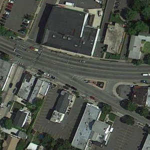
In the example below, the multi-lane surface street is known as Main Street to the west and Atlantic Ave to the east. The name change occurs when Main St branches off as a regular surface street.
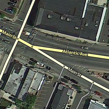
The description above is how a human would probably describe the situation, but as you can see in the image above, a more technical description would be that Main St travels in a perfectly straight line and Atlantic Ave branches off of it. But if we map it that way in the editor, we create a major problem.
Since the multi-lane segment of Main St and the regular street segment of Main St have the same name, the routing engine automatically considers that to be "straight". If the two sections line up in a straight line the way they appear from the sky, then we are reinforcing the idea that "straight" is Main St. to Main St.
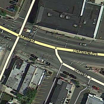
But as a typical driver would want, "straight" should be the path that remains on the multi-lane roadway, regardless of what the name is. To make sure the routing engine understands the proper treatment of the junction, we have to be deliberate with the segment geometry of all three involved segments. We end up with something like this:
Now the geometric definition of straight is the multi-lane portion of Main St. onto Atlantic Ave., since we have made that transition as close to zero degrees as possible. The regular street portion of Main St. now branches off at an angle close to 90 degrees. The routing engine should recognize that a turn is required. So the result is that Main St. to Atlantic Ave. has no announced turn, and multi-lane Main St. to surface road Main St. has a turn announced. Exactly what most drivers would expect in the real world.
No Outlet Roads
Roads which only have one way in and one way out can present challenges to the routing server, although they seem simple to our minds.
Dead Ends
Dead Ends (a.k.a. No Exit, Closed, No Through Road, No Outlet) are road segments that simply end, with no continuation or connections at one end. In some areas, a Dead End may be synonymous with a Cul-de-sac. In the US, a "No Outlet" sign may be used to indicate a road which itself is not a dead end, but it only connects to other dead end roads. It can also be used as a "friendlier" alternative to the typical Dead End sign.
Within the Map Editor it is possible to represent a dead end road with multiple segments if there are private driveways or parking lot roads mapped and connected. In that case, only the very last segment is considered the dead end segment.
Make sure that there is a junction node (not just a geometry node) at the very end of the segment. This is necessary to ensure proper routing out of the segment.
Cul-de-sacs
See also: Cul-de-sac article on Wikipedia
A Cul-de-sac (a.k.a. Court in the US) is a common treatment of a dead end street in a residential neighborhood.
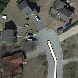
In almost every situation, a cul-de-sac should be treated exactly as a dead end street, with the final junction node in the center of the bulb of the cul-de-sac. Be sure the free end of the final road segment has small blue diamond displayed at the tip (when not editing or selecting the segment.) If there is no blue diamond, please correct it by following the steps for fixing dead ends.
The cul-de-sac below, with a small island, should be treated as a basic dead end with no loop. The island can be ignored, as there is no significant routing question for the driver once they get to the cul-de-sac.
However, if the cul-de-sac has a very large bulb with a large island in the middle, it may better be treated as a Loop. If you see an island, but are not sure if it is significant, leave the Loop out. If "Missing Road" errors occur then add a Loop.
Loops
Loops are roads that you can enter, and without reversing course, end up at the same place you started.
An important Map Editor rule is: a road segment must not start and end on the same junction node.
If this rule is not followed, the routing server will have difficulty in providing routes into and out of the loop. Any loop broken into two segments by a junction will not have this problem.
Hopefully there will be another roadway along the loop road which you can map, which will break the loop into two pieces. If there are no interruptions to the loop and the entire loop is represented by one road segment that connects with itself, we must insert a superfluous junction node along the loop segment. The specific location does not matter, but most people put it near the half-way point of the segment.
NOTE: It is very easy for an editor to find the extra junction node, assume it is truly superfluous, and delete it! This problem is magnified if the loop road is large or shaped so it is not obvious that it is a loop. One solution is to identify a path or driveway branching from the loop road and add it to the map, forcing a 3-way junction that would be less likely to be deleted.
Roundabouts and Traffic Circles
Please see the Roundabout page for a full discussion of this special type of junction.
At-Grade Connectors
Don't set these segments as ramps! Watch out for all of the turns you need to restrict. For a full discussion, see the At-Grade Connectors page.
Ramps
Ramps have a very specific purpose in Waze. They are intended to connect segments of Minor Highways, Major Highways, and Freeways to roads where there are no at-grade crossings.
When to use ramps
The following conditions must be met for the use of ramps to be appropriate:
- Two roads cross over/under each other with no at-grade junction
- At least one of the roads are of these types
- Minor Highway
- Major Highway
- Freeway
- Ramp
If the above requirements are not satisfied, you may be dealing with an At-Grade Connector.
How complex should ramps be?
Rule #1 is still simpler is better. If there is no large distance between paths at the end of a ramp (either into or out of the ramp), a single segment connecting to a single junction node is all that is needed. The existence of a painted, concrete, or grass island is NOT enough of a reason to split a ramp into multiple ramps.
When paths at the end of the ramp deviate significantly in distance, regardless of the existence of any type of island, then multiple ramps should be used.
Highway/Freeway Junctions
These are junctions involving the three Highway/Freeway road types - Minor Highway, Major Highway, and Freeway -- as well as their Ramps.
Specific examples of how to handle common junction types are provided in later sections. All of those examples use the basic building blocks provided here.
If you are unsure what road type you should use, refer to the article on road types for more information.
Highway/Freeway Exits
It is a basic Exit situation when a "straight" direction is obvious to a driver and navigation instructions are only needed for the non-straight direction (the exit.) If navigation instructions are required for both directions, see the Highway/Freeway Splits section below.
Structure
To be treated as a basic Exit, the following must be true:
- The entering segment and one exiting segment must be one of the three Highway/Freeway types
- The Highway/Freeway exiting segment must have close to a zero degree departure angle from the entering segment
- The other exiting segment must be of the type Ramp
- The Ramp exiting segment must have a departure angle of between 20 and 30 degrees from the entering segment
When those conditions are met, the navigation will present an "Exit Right/Left" instruction when the ramp is to be used, and will remain silent when the exiting Highway/Freeway segment is to be used.
Naming
The Highway/Freeway segments before and after the junction should be named the same. The ramp segments should be named in accordance with the best practices in your location.
Editors covering areas that do not have specific best practices should review the existing guides for other areas, and determine which best matches the roadways of your area.
Highway/Freeway Splits
A Highway/Freeway Split is when a Highway/Freeway segment meets at a junction with two other Highway/Freeway segments and there is no obvious straight through direction to a driver.
Structure
To receive a navigation instruction for both branches of a split, the following must be true:
- All segments must be one of the three Highway/Freeway Types
- All segments must have names which are different from each other
- The two exiting segments must have departure angles of 20 to 30 degrees from the entering segment
With those conditions met, the junction will present "Keep Left" and "Keep Right" navigation instructions using the name of the appropriate exiting segment.
Naming
The primary rule is that all 3 segments at the junction must have different names. That can be accomplished in one of two ways:
- Using road names alone - It is an easy situation if all three roads which connect have different names. If "Highway A" splits into "Highway B" and "Highway C", then that is all we need to have a properly functioning split.
- Using signs and way-finders - If one of the branches of the split has the same name as the entering segment, we must create uniqueness at the junction. If "Highway X" splits off from "Highway Y" and "Highway X" continues as the other branch, the preferred approach is to use named Way-finder Segments.
Wayfinder Segments
Here we show Highway Y splitting off from Highway X. By labeling segments with the information available on the road signs at the split, we have achieved uniqueness and provided additional useful information (the destination cities) to the driver.
Do not name the entire segment leaving the junction should with the way-finder info. Instead split the segment, with a short one named with the way-finder information right at the junction, and the long one retaining the name of the road. This is so we are less likely to see a long way-finder name on the client map.
A rule of thumb for the way-finder segments is to make them 15 to 20 meters long. This keeps the segment small so we are less likely to see it in the client, but keeps it long enough to find and manipulate in the map editor.
Ramp to Ramp Splits
A ramp may itself split and branch into two directions. If this is the case, "Exit Right" and "Exit Left" will be announced using the name of the appropriate exiting segment in all cases.
Structure
Naming
If ramps are unnamed, the name of a subsequent ramp will propagate backwards. In the example above, if the two ramps exiting the junction are named, the ramp entering the junction can be left unnamed. Then any turn into the first ramp would use the name of the appropriate exiting ramp.
Example: Assume the two ramps exiting the junction are named "DestinationLeft" and "DestinationRight". Assume the ramp that enters the junction is unnamed. Assume you need to "Exit Right" onto the unnamed ramp. If you are headed to "DestinationLeft", navigation would tell you:
- Exit Right to Destination Left
- Exit Left to Destination Left
Using unnamed ramps is very useful to provide sufficient notification of an approaching decision point as long as the names of both ramp splits are visible on signs at the start of the initial ramp.
Example of good use of unnamed ramps:
- Initial Exit Sign: to City A and City B
- Destination Left Sign: to City A
- Destination Right Sign: to City B
Result: An unnamed initial ramp will provide accurate and informative navigation instructions to the driver.
Example of poor use of unnamed ramps:
- Initial Exit Sign: to Downtown
- Destination Left Sign: to Downtown
- Destination Right Sign: to Center St
Result: An unnamed ramp may create confusion since both Destination ramp names are NOT listed on the initial exit sign. In this case the initial ramp should be named.
Example of modified use of unnamed ramps:
- Initial Exit Sign: Exit 70A-B to City A and City B
- Destination Left Sign: to City A
- Destination Right Sign: to City B
- Destination Left name in Waze: Exit 70A: City A
- Destination Right name in Waze: Exit 70B: City B
Result: By using a modified name for the destination ramps, we have combined information from two sets of signs to generate the advance notice a driver may need to prepare for a decision point.
Limited Access Interchanges
Please see the Limited Access Interchange Style Guide.
Special Cases
Transitions
A transition is a non-junction depicted using a junction node.
Valid examples of where to use a Transition node include:
- Road name changes
- City Limits
- Road Direction changes
- Part of a Loop Road
There may be exiting Transition nodes on the map for other reasons (left over after a connecting road was deleted, due to the original base map import when things such as rivers and streams created junctions, etc.).
As long as we are certain it is not a valid Transition node, a superfluous junction node may be deleted. Doing so will simplify the map, eliminate turn restrictions to maintain, and ease computing resources needed to calculate routes in the area. Also consider removing the geometry node which will replace the junction node you delete if that geometry node is not needed.
Roads to Nowhere
In certain situations it may be necessary to add road segments that are otherwise un-drivable and unneeded in order to provide accurate navigation instructions.
Actual
A valid use of this technique is at the temporary end of a freeway. As a freeway is built, it is often opened in sections at a time, up to a certain exit. If we map this as simply a freeway segment leading to a ramp segment for that last exit, no announcement will be made for that final exit no matter what we name the exit ramp.
This can be confusing if the ramp is set up as a properly signed and numbered exit especially if a driver is traveling a long distance on this freeway. Imagine traveling down a freeway and seeing your next instruction is to "turn left at Main St." You would probably wonder if there was a map error since you shouldn't be making left turns off of a freeway in most cases.
If we map even just a little of the future path of the freeway, this gives the routing engine a junction which will generate an "exit" instruction at the end of the freeway thus eliminating any confusion.
Conversely, if we do NOT want an exit instruction at the end of a freeway, ensure there are no road segments extending past the final exit to ensure the final exit is the only path out of the final freeway segment.
Fake
(coming soon)
Offset Roads
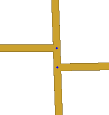
Sometimes you will find two roads which cross where one does not quite line up exactly from one side to the other.
There are a few things we need to look at in this situation.
- Do the roads actually line up in reality? If so we need to modify the junction to be a basic 4-way junction.
- Do the roads ALMOST line up in reality? If you were giving instructions to a person and would tell them to go straight with no mention of any slight turn or jog, then we want to make it into a 4-way junction. You may need to "split the difference" and not follow the centerline of either road to achieve this. The angles are exaggerated in this next example to show how the junction is forced to be close to 90 degrees, then we taper to the true centerlines of the roads. In practice this can be much more gradual and/or only done while zoomed in very close.


- Finally, is there a true separation between the roads? Would you need to say for example "turn left then make an immediate right"? If so then we will want to leave the junction such that the two sides do not align.

Since we want to avoid very short segments of road (the GPS chips in consumer devices can be very inaccurate which may make it seem that a driver skipped right over a short segment which will result in automated map errors and possible route recalculations in the client), it may be wise to shift the side roads as far apart from each other as possible with them still in the proper location (along the far curb lines for a residential street for example). This will maximize the length of the short segment between the side roads.


